Low Cost Auto Flusher
Problem Statement
Design and develop a low-cost automatic flusher system using readily available components. The objective is to create an efficient, cost-effective solution for automated flushing systems that can be implemented in various settings, ensuring hygiene and convenience. This system is developed without using microcontrollers, relying solely on logic gates and basic electronic components.
Circuit Design
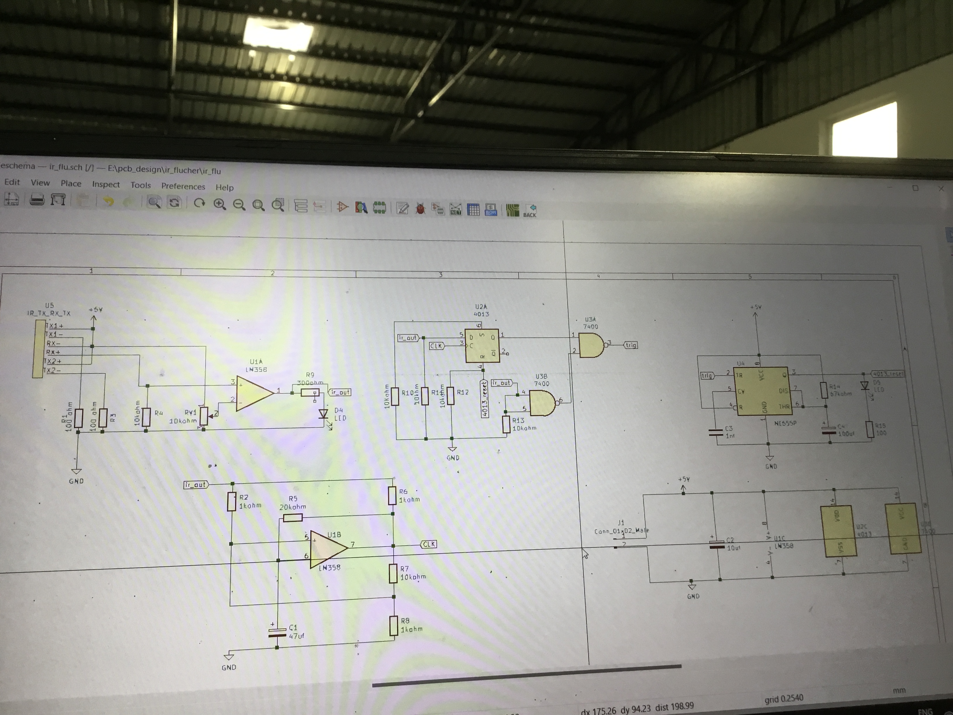
The schematic diagram of the auto flusher circuit, illustrating the configuration of components such as the IR sensors, operational amplifiers, and logic gates. This design enables the detection of a user’s presence and activates the flushing mechanism accordingly.
Explanation
IR Sensors: Detect the presence of a user. Operational Amplifiers (LM358): Amplify the signals from the IR sensors. Logic Gates (74 series ICs): Process the signals to control the flushing mechanism. 555 Timer IC: Used for generating timing pulses required for the flushing operation. Power Supply: Provides the necessary voltage for circuit operation.
PCB Layout
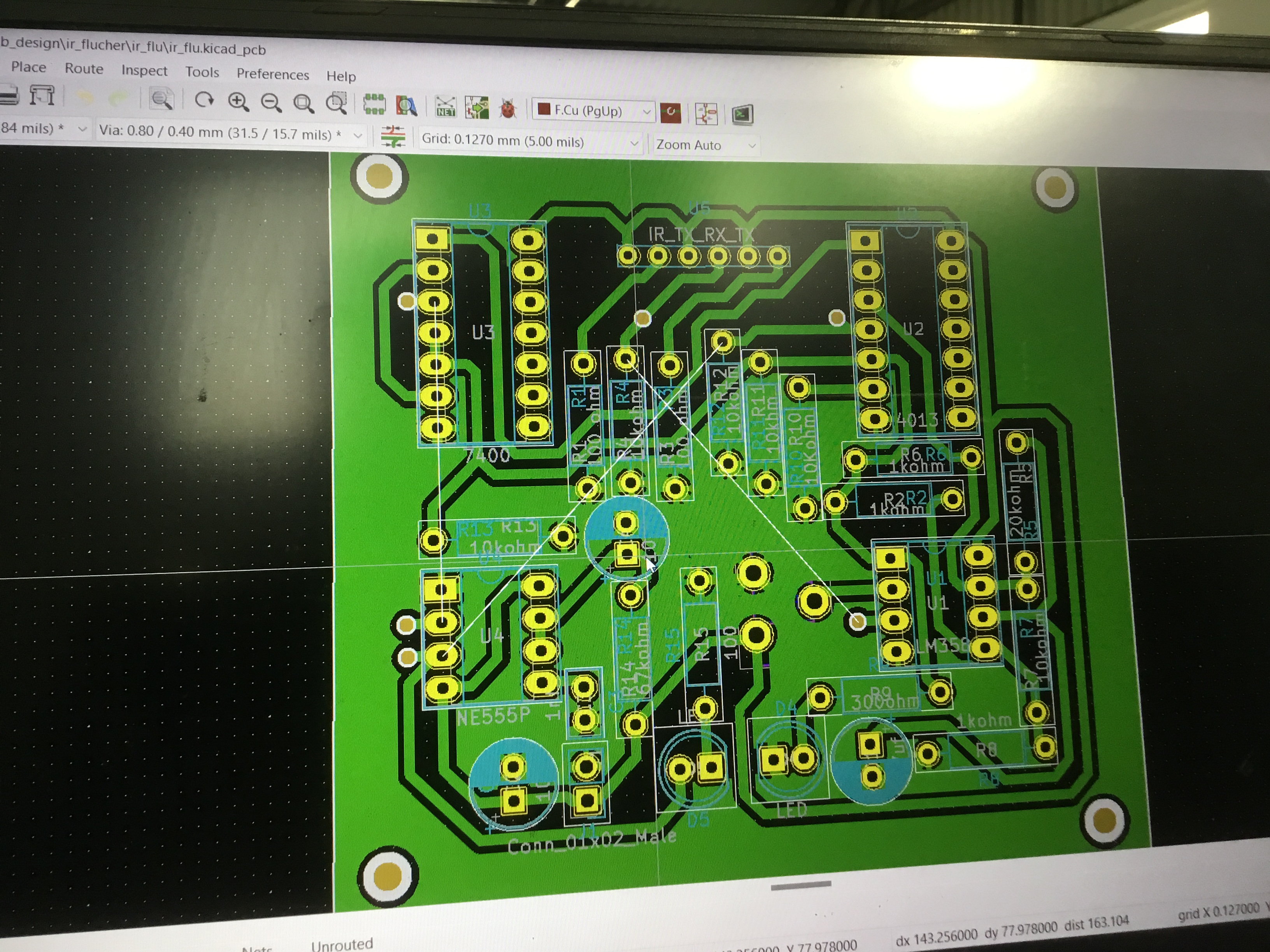
The printed circuit board (PCB) layout for the auto flusher, showing the placement of components and the routing of electrical connections. The layout ensures compactness and efficiency in the design.
The fully assembled PCB, ready for integration into the auto flusher system. The assembled board includes all the necessary components soldered in place and is tested for functionality.